Nano-Hexapod Struts mounting - Test Bench
Table of Contents
This report is also available as a pdf.
1 Mounting Bench
A mounting bench is used to greatly simply the mounting of the struts as well as ensuring the correct strut length and coaxiality of the flexible joint’s interfaces. This is very important in order to not loose any stroke when the struts will be mounted on the nano-hexapod.
A CAD view of the mounting bench is shown in Figure 1.
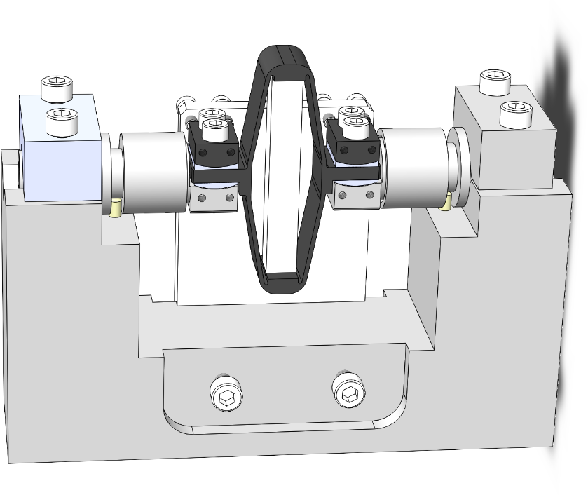
Figure 1: CAD view of the mounting bench
The main part of the bench is here to ensure both the correct strut length and strut coaxiality as shown in Figure 2.

Figure 2: Useful features of the main mounting element
The tight tolerances of this element has been verified as shown in Figure 1 and were found to comply with the requirements.
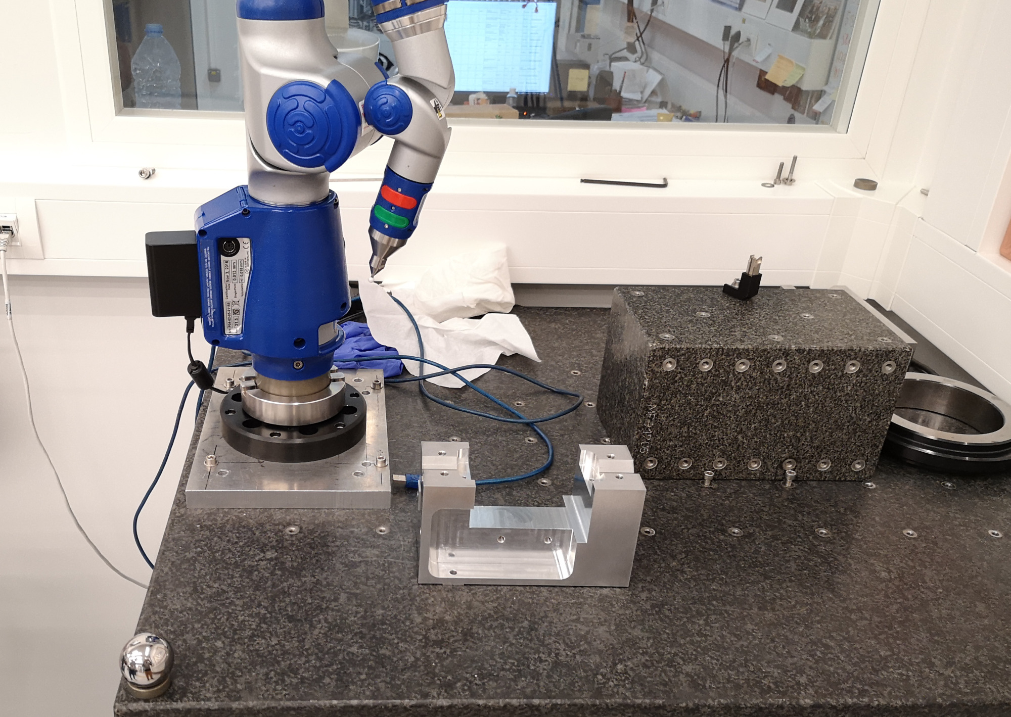
Figure 3: Dimensional verifications of the mounting bench tolerances
The flexible joints are rigidly fixed to cylindrical tools shown in Figure 4 which are then mounted on the mounting tool shown in Figure 2. This cylindrical tool is here to protect the flexible joints when tightening the screws and therefore applying large torque.
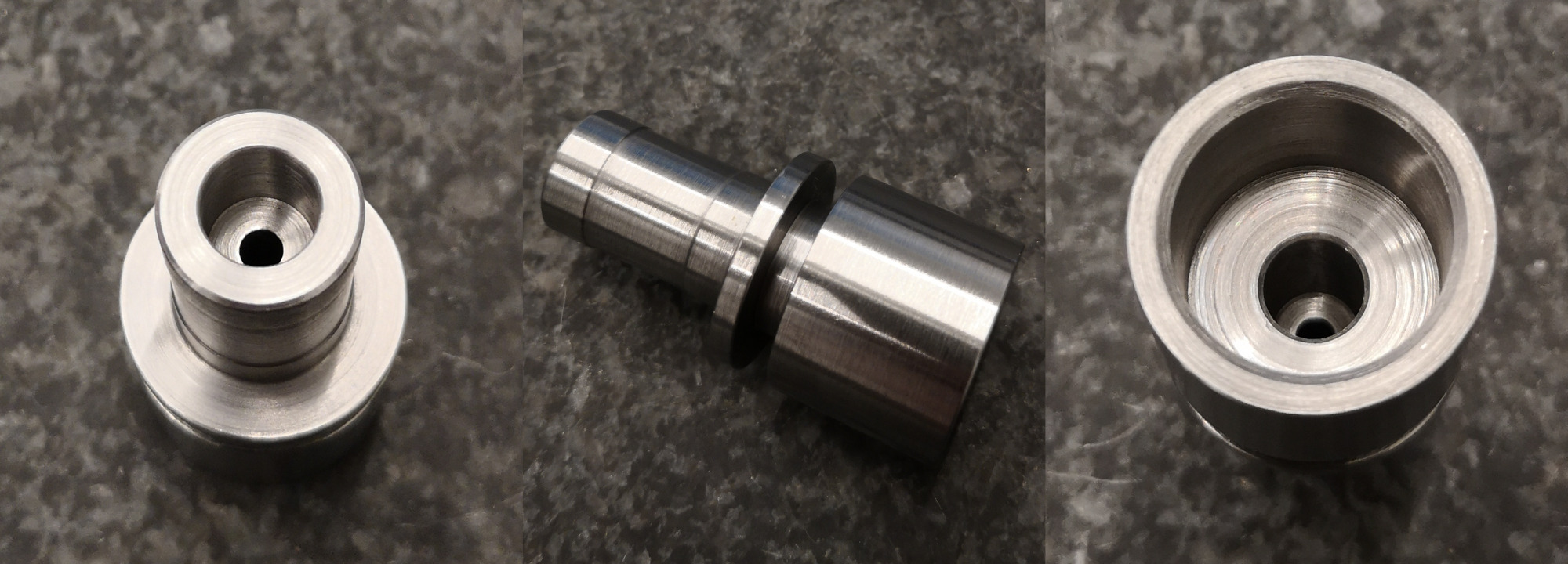
Figure 4: Cylindrical mounting elements
2 Mounting Procedure
The mounting procedure is as follows:
- Screw flexible joints inside the cylindrical interface element shown in Figure 4 (Figure 5)
- Fix the two interface elements. One of the two should be clamped, the other one should have its axial rotation free. Visually align the clamped one horizontally. (Figure 6)
- Put cylindrical washers, APA and interface pieces on top of the flexible joints (Figure 7)
- Put the 4 screws just in contact such that everything is correctly positioned and such that the “free” flexible joint is correctly oriented
- Put the 8 lateral screws in contact
- Tighten the 4 screws to fix the APA on the two flexible joints (using a torque screwdriver)
- Remove the 4 laterals screws
- (optional) Put the APA horizontally and fix the encoder and align it to maximize the contrast (Figure 8)
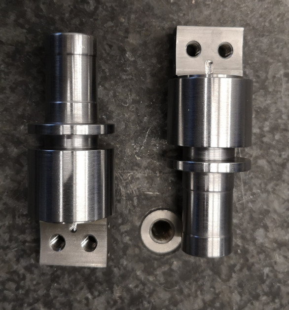
Figure 5: Step 1 - Flexible joints fixed on the cylindrical interface elements
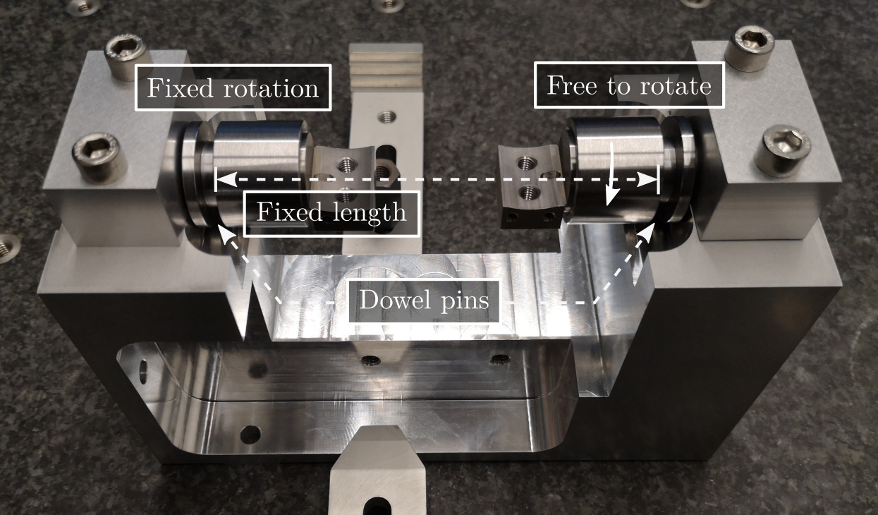
Figure 6: Step 2 - Cylindrical elements fixed on the bench
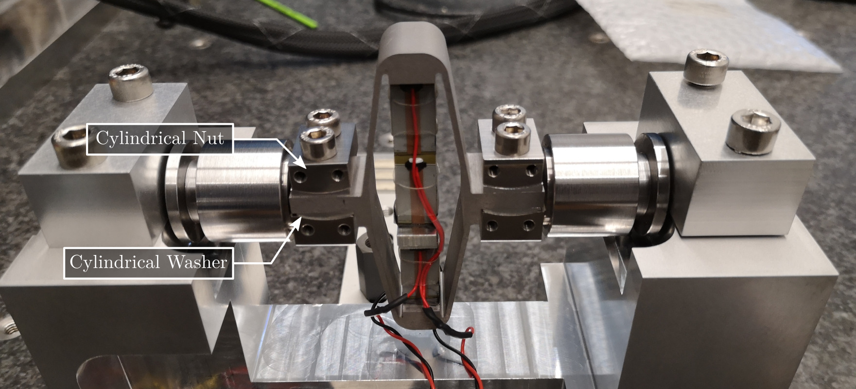
Figure 7: Step 3 - Mount the nuts, washers and APA
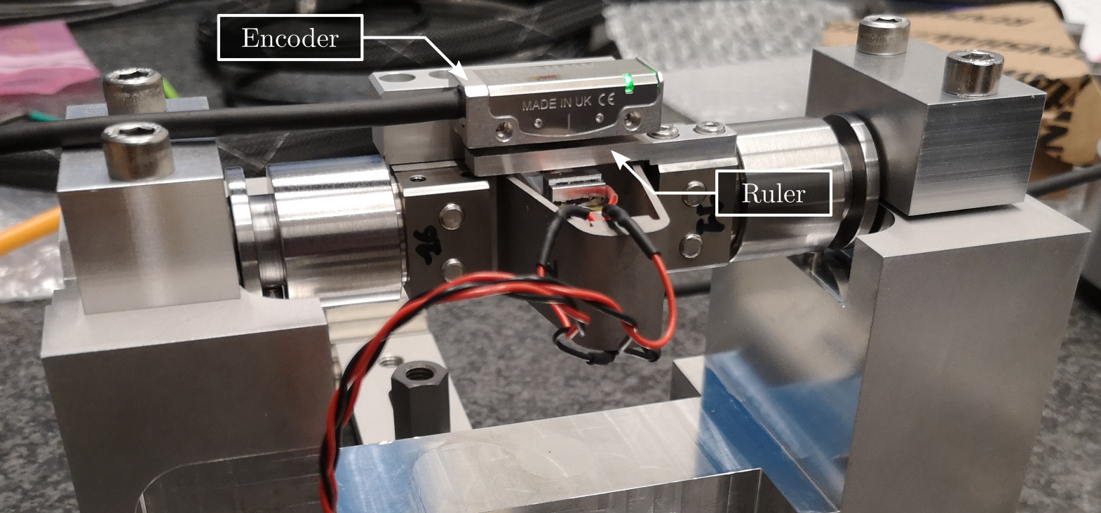
Figure 8: Last step - Align the encoder on the strut
3 Mounted Struts
After removing the strut from the mounting bench, we obtain a strut with ensured coaxiality between the two flexible joint’s interfaces (Figure 9).
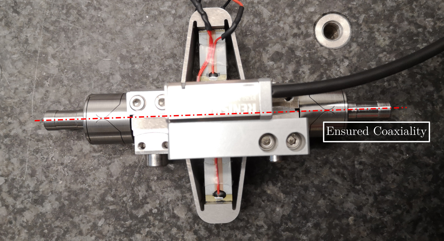
Figure 9: Mounted Strut with ensured coaxiality