Measurement of Piezoelectric Amplifiers
Table of Contents
The following two voltage amplifiers are tested:
The piezoelectric actuator under test is an APA95ML from Cedrat technology (doc). It contains three stacks with a capacitance of \(5 \mu F\) each that can be connected independently to the amplifier.
This document is divided into the following sections:
- Section 1: The effect of a change in load capacitance on the amplifier dynamics is studied
- Section 2: The effect on the voltage level on the amplifier dynamics is studied
- Section 3: The dynamics of the E-505 and LA75B are compared
- Section 4: The output impedance of both amplifiers are measured
- Section 5: The effect of the internal filters of the E-505 on its dynamics is studied
1 Effect of a change of capacitance
1.1 Cedrat Technology
Load Data
piezo1 = load('cedrat_la75b_med_1_stack.mat', 't', 'V_in', 'V_out');
piezo2 = load('cedrat_la75b_med_2_stack.mat', 't', 'V_in', 'V_out');
piezo3 = load('cedrat_la75b_med_3_stack.mat', 't', 'V_in', 'V_out');
Compute Coherence and Transfer functions
Ts = 1e-4;
win = hann(ceil(0.1/Ts));

[tf_1, f] = tfestimate(piezo1.V_in, piezo1.V_out, win, [], [], 1/Ts);
[co_1, ~] = mscohere(piezo1.V_in, piezo1.V_out, win, [], [], 1/Ts);

[tf_2, ~] = tfestimate(piezo2.V_in, piezo2.V_out, win, [], [], 1/Ts);
[co_2, ~] = mscohere(piezo2.V_in, piezo2.V_out, win, [], [], 1/Ts);

[tf_3, ~] = tfestimate(piezo3.V_in, piezo3.V_out, win, [], [], 1/Ts);
[co_3, ~] = mscohere(piezo3.V_in, piezo3.V_out, win, [], [], 1/Ts);
We remove the phase delay due to the time delay of the ADC/DAC:
angle_delay = 180/pi*angle(squeeze(freqresp(exp(-s*Ts), f, 'Hz')));
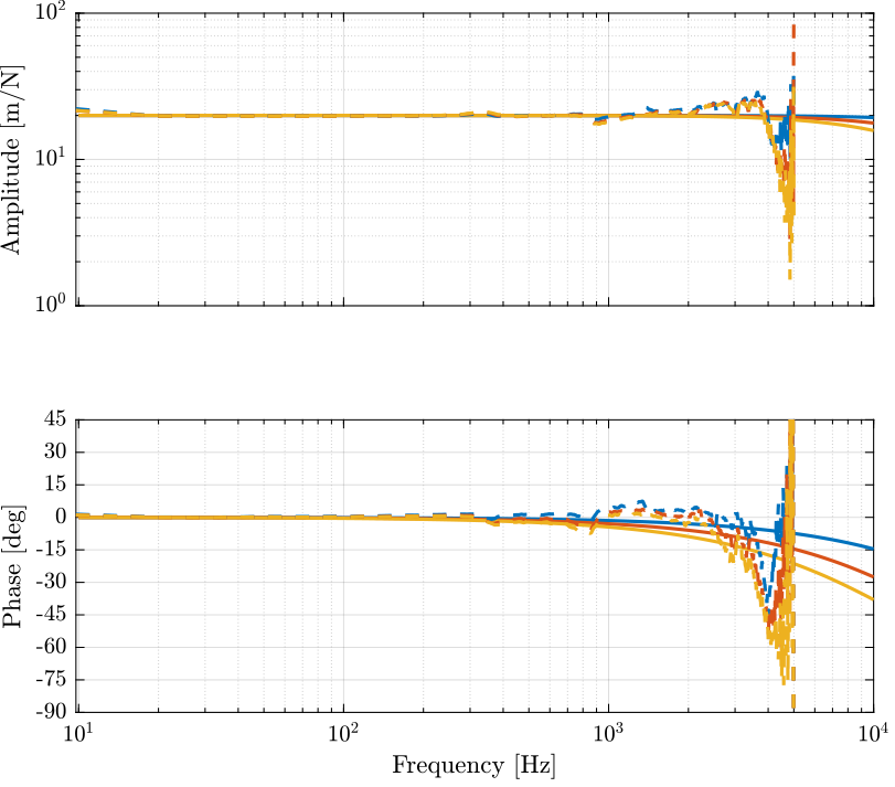
Figure 1: Effect of a change of the piezo capacitance on the Amplifier transfer function
1.2 PI
piezo1 = load('pi_505_high.mat', 't', 'V_in', 'V_out');
piezo2 = load('pi_505_high_2_stacks.mat', 't', 'V_in', 'V_out');
piezo3 = load('pi_505_high_3_stacks.mat', 't', 'V_in', 'V_out');
Ts = 1e-4;
win = hann(ceil(0.1/Ts));

[tf_1, f] = tfestimate(piezo1.V_in, piezo1.V_out, win, [], [], 1/Ts);
[co_1, ~] = mscohere(piezo1.V_in, piezo1.V_out, win, [], [], 1/Ts);

[tf_2, ~] = tfestimate(piezo2.V_in, piezo2.V_out, win, [], [], 1/Ts);
[co_2, ~] = mscohere(piezo2.V_in, piezo2.V_out, win, [], [], 1/Ts);

[tf_3, ~] = tfestimate(piezo3.V_in, piezo3.V_out, win, [], [], 1/Ts);
[co_3, ~] = mscohere(piezo3.V_in, piezo3.V_out, win, [], [], 1/Ts);
We remove the phase delay due to the time delay of the ADC/DAC:
angle_delay = 180/pi*angle(squeeze(freqresp(exp(-s*Ts), f, 'Hz')));
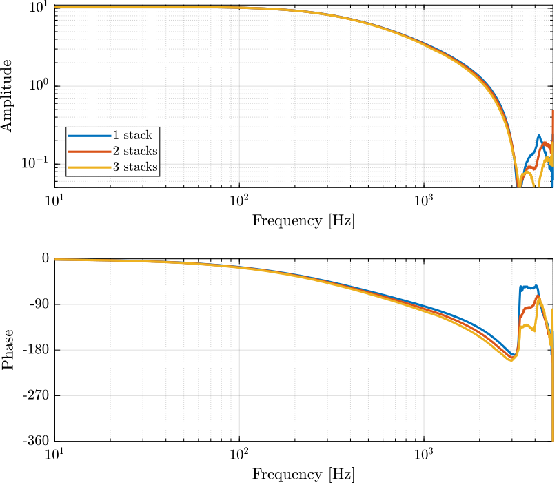
Figure 2: Effect of a change of the piezo capacitance on the Amplifier transfer function
2 Effect of a change in Voltage level
2.1 Cedrat Technology
hi = load('cedrat_la75b_high_1_stack.mat', 't', 'V_in', 'V_out');
me = load('cedrat_la75b_med_1_stack.mat', 't', 'V_in', 'V_out');
lo = load('cedrat_la75b_low_1_stack.mat', 't', 'V_in', 'V_out');
Ts = 1e-4;
win = hann(ceil(0.1/Ts));

[tf_hi, f] = tfestimate(hi.V_in, hi.V_out, win, [], [], 1/Ts);
[co_hi, ~] = mscohere(hi.V_in, hi.V_out, win, [], [], 1/Ts);

[tf_me, ~] = tfestimate(me.V_in, me.V_out, win, [], [], 1/Ts);
[co_me, ~] = mscohere(me.V_in, me.V_out, win, [], [], 1/Ts);

[tf_lo, ~] = tfestimate(lo.V_in, lo.V_out, win, [], [], 1/Ts);
[co_lo, ~] = mscohere(lo.V_in, lo.V_out, win, [], [], 1/Ts);
We remove the phase delay due to the time delay of the ADC/DAC:
angle_delay = 180/pi*angle(squeeze(freqresp(exp(-s*Ts), f, 'Hz')));
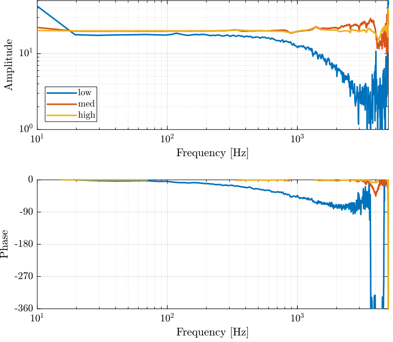
Figure 3: Effect of a change of voltage level on the Amplifier transfer function
2.2 PI
hi = load('pi_505_high.mat', 't', 'V_in', 'V_out');
lo = load('pi_505_low.mat', 't', 'V_in', 'V_out');
Ts = 1e-4;
win = hann(ceil(0.1/Ts));

[tf_hi, f] = tfestimate(hi.V_in, hi.V_out, win, [], [], 1/Ts);
[co_hi, ~] = mscohere(hi.V_in, hi.V_out, win, [], [], 1/Ts);

[tf_lo, ~] = tfestimate(lo.V_in, lo.V_out, win, [], [], 1/Ts);
[co_lo, ~] = mscohere(lo.V_in, lo.V_out, win, [], [], 1/Ts);
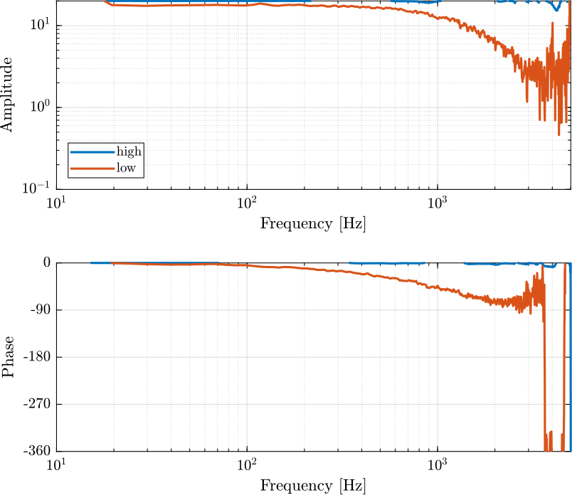
Figure 4: Effect of a change of voltage level on the Amplifier transfer function
3 Comparison PI / Cedrat
3.1 Results
ce_results = load('cedrat_la75b_high_1_stack.mat', 't', 'V_in', 'V_out');
pi_results = load('pi_505_high.mat', 't', 'V_in', 'V_out');
Ts = 1e-4;
win = hann(ceil(0.1/Ts));

[tf_ce, f] = tfestimate(ce_results.V_in, ce_results.V_out, win, [], [], 1/Ts);
[tf_pi, ~] = tfestimate(pi_results.V_in, pi_results.V_out, win, [], [], 1/Ts);
We remove the phase delay due to the time delay of the ADC/DAC:
angle_delay = 180/pi*angle(squeeze(freqresp(exp(-s*Ts), f, 'Hz')));
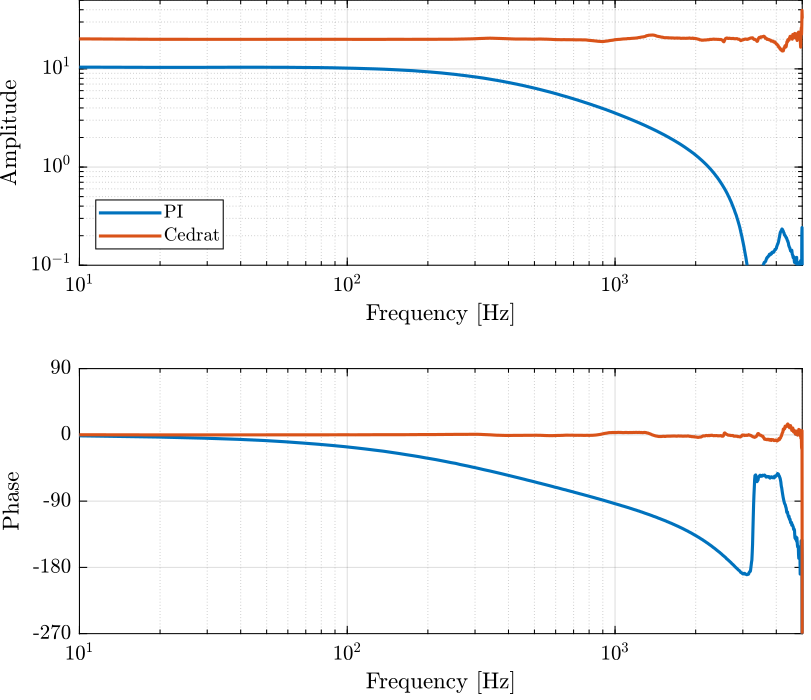
Figure 5: Comparison of the two Amplifier transfer functions
4 Impedance Measurement
The goal is to experimentally measure the output impedance of the voltage amplifiers.
To do so, the output voltage is first measure without any load (\(V\)). It is then measure when a 10Ohm load is used (\(V^\prime\)).
The load (\(R = 10\Omega\)) and the internal resistor (\(R_i\)) form a voltage divider, and thus: \[ V^\prime = \frac{R}{R + R_i} V \]
From the two values of voltage, the internal resistor value can be computed: \[ R_i = R \frac{V - V^\prime}{V^\prime} \]
4.1 Cedrat Technology
4.1.1 Compute Impedance
R = 10;    % Resistive Load used [Ohm]
V = 0.998; % Output Voltage without any load [V]
Vp = 0.912; % Output Voltage with resistice load [V]
R * (V - Vp)/Vp;
0.94298
R = 47;    % Resistive Load used [Ohm]
V = 4.960; % Output Voltage without any load [V]
Vp = 4.874; % Output Voltage with resistice load [V]
R * (V - Vp)/Vp;
0.8293
4.1.2 Effect of Impedance on the phase drop
C_1 = 5e-6; % Capacitance in [F]
C_2 = 10e-6; % Capacitance in [F]
C_3 = 15e-6; % Capacitance in [F]

Ri = R * (V - Vp)/Vp; % Internal resistance [Ohm]
G0 = 20;

G_1 = G0/(1+Ri*C_1*s);
G_2 = G0/(1+Ri*C_2*s);
G_3 = G0/(1+Ri*C_3*s);
Figure 6: Effect of a change of the piezo capacitance on the Amplifier transfer function
4.2 PI
R = 10;    % Resistive Load used [Ohm]
V = 1.059; % Output Voltage without any load [V]
Vp = 0.828; % Output Voltage with resistice load [V]
R * (V - Vp)/Vp
2.7899
R = 10;    % Resistive Load used [Ohm]
V = 2.092; % Output Voltage without any load [V]
Vp = 1.637; % Output Voltage with resistice load [V]
R * (V - Vp)/Vp
2.7795
5 Effect of filters configuration on the PI-E505 dynamics
5.1 PI
Three measurements are done:
- Slew Rate limitation at maximum
- Slew Rate limitation at minimum
- Notch Filter at maximum frequency
pi_sr_min       = load('pi_slew_rate_min.mat');
pi_sr_max       = load('pi_slew_rate_max.mat');
pi_sr_max_notch = load('pi_slew_rate_max_notch_high.mat');
pi_sr_load      = load('pi_slew_rate_max_notch_high_2stacks.mat');
Ts = 1e-4;
win = hann(ceil(0.1/Ts));

[tf_sr_min, f] = tfestimate(pi_sr_min.V_in, pi_sr_min.V_out, win, [], [], 1/Ts);
[tf_sr_max, ~] = tfestimate(pi_sr_max.V_in, pi_sr_max.V_out, win, [], [], 1/Ts);
[tf_sr_max_notch, ~] = tfestimate(pi_sr_max_notch.V_in, pi_sr_max_notch.V_out, win, [], [], 1/Ts);
[tf_sr_load, ~] = tfestimate(pi_sr_load.V_in, pi_sr_load.V_out, win, [], [], 1/Ts);
angle_delay = 180/pi*angle(squeeze(freqresp(exp(-s*Ts), f, 'Hz')));
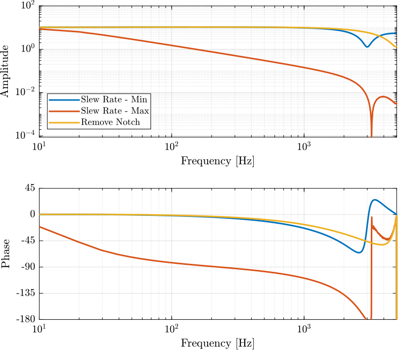
Figure 7: Effect of a change in the slew rate limitation and notch filter
5.2 Transfer function of the Voltage Amplifier
The identified transfer function still seems to match the one of a notch filter at 5kHz.
w_nf = 2*pi*5e3; % Notch Filter Frequency [rad/s]
G = 10.5*(s^2 + 2*w_nf*0.12*s + w_nf^2)/(s^2 + 2*w_nf*s + w_nf^2);
5.3 With Load
R = 2.78; % Output Impedance [Ohm]
C = 9e-6; % Load capacitance [F]

G_amp = 10/(1 + s*R*C);