NASS - Short Stroke Metrology
Table of Contents
This report is also available as a pdf.
The goal of this document is to analyze the feasibility of a short stroke metrology system for the NASS using fixed interferemoter and the same reflector as for the long stroke metrology system.
It is structured as follow:
- Section 1: the meaurement principle is described.
- Section 2: the requirements for the interferometers measuring translations are described
- Section 3: the same is done for the rotations
1 Measurement Principle
Here are the defined wanted displacement of the reflector that should be inside the measurement stroke of the metrology system. The defined translations and rotations are defined with respect to the frame shown in Figure 1.
d_x = 0;     % Wanted translation of the reflector in the x direction [m]
d_y = 1e-3;  % Wanted translation of the reflector in the y direction [m]
d_z = 1e-3;  % Wanted translation of the reflector in the z direction [m]
R_x = 10e-3; % Wanted rotation of the reflector along the x axis [rad]
R_y = 0;     % Wanted rotation of the reflector along the y axis [rad]
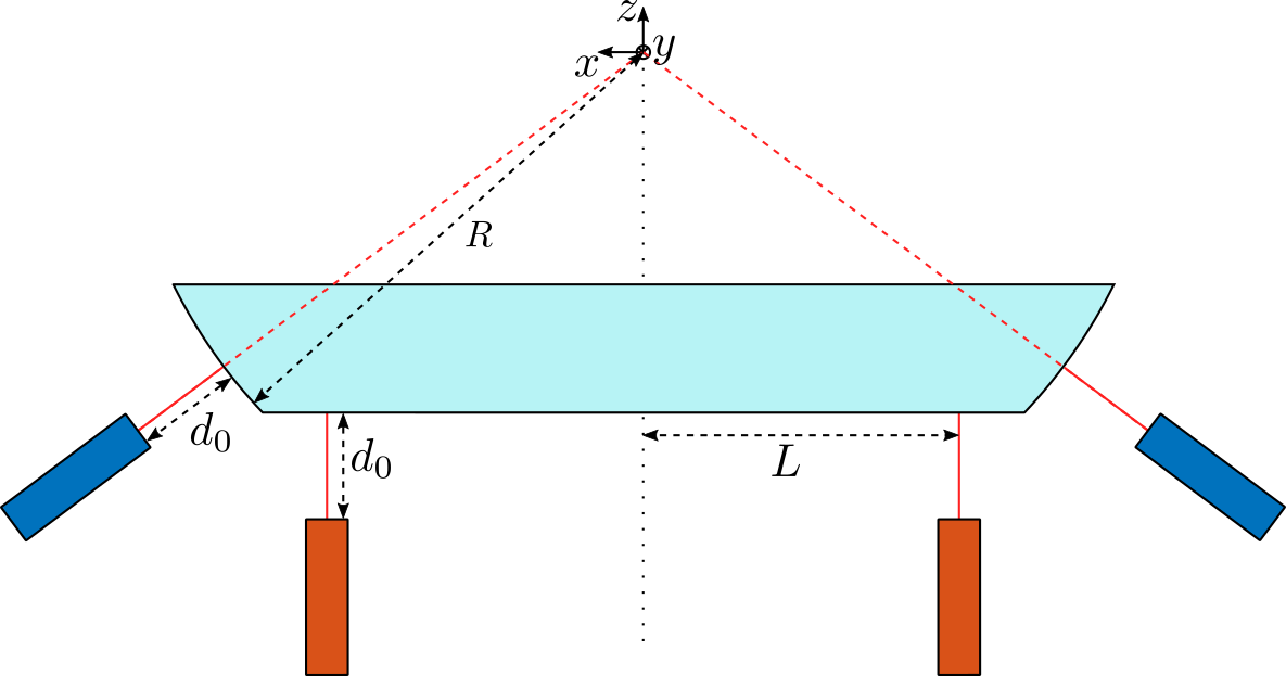
Figure 1: Short Stroke Metrology - Concept. Blue interferometers are used to measure the X-Y-Z motion of the reflector. Red interferometers are used to measure tilt motion of the reflector.
Here are the approximate dimensions shown in Figure 1:
- \(d_0 \approx 10\,[mm]\)
- \(L \approx 150\,[mm]\)
- \(R \approx 250\,[mm]\)
d0 = 10e-3; % [m]
L = 150e-3; % [m]
R = 250e-3; % [m]
2 X-Y-Z measurement
The geometry for the interferometers measuring translations is shown in Figure 2:
- \(R = 250\,[mm]\)
- \(d_0 > 10\,[mm]\)
- \(d_x = \pm 1\,[mm]\)
- \(d_y = \pm 1\,[mm]\)
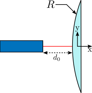
Figure 2: Interferometers that are measuring translation
The angle of the reflected beam is approximately equal to:
\begin{equation} \theta \approx 2 \frac{d_y}{R} \end{equation}And we obtain:
\[ \theta \approx 8.0\,[mrad] \]
| Specification | Value |
|---|---|
| Axial Acceptance | \(\pm 1\,[mm]\) |
| Angular Acceptance | \(\pm 8\,[mrad]\) |
| Distance to target | \(10\,[mm]\) |
| Target | Convex with \(R = 250\,[mm]\) |
3 Tilt measurement
The tilt \(\theta\) of the flat mirror is directly equal to the tilt of the reflector. However, the \(z\) displacement on the flat part is equal to:
\begin{equation} z \approx d_z + L \theta_y \end{equation}And we obtain:
\[ z \approx 2.5\,[mm] \]
The geometry for the interferometers measuring rotations is shown in Figure 3:
- \(d_0 > 10\,[mm]\)
- \(\theta = \pm 10\,[mrad]\)
- \(z = \pm 2.5\, [mm]\)

Figure 3: Interferometers that are measuring tilt
| Specification | Value |
|---|---|
| Axial Acceptance | \(\pm 2.5\,[mm]\) |
| Angular Acceptance | \(\pm 10\,[mrad]\) |
| Distance to target | \(10\,[mm]\) |
| Target | Flat mirror |